
Windscreen washers, more welding and handbrake cable adjustments
Click on the images to enlarge
I don't know how I managed it but somehow my Mini's annual MOT falls in December, which is not ideal if work needs to be done as it's usually freezing outside at this time of year.
To get the car ready for an MOT I tend to use the Haynes manual combined with an old MOT sheet from a previous failure. Although useful at the time to tell you what needed fixing in order to get through a re, they are also useful in that they tell you what the er will be looking for this time around.
Feeling fairly confident, I took the car to the MOT ing station where I was once again presented with another failure sheet (which I will use for next years pre-MOT checks).
There were five entries on the failure sheet:
- Two holes located near a seatbelt mounting point
- A hole near a subframe mounting point
- Ineffective windscreen washer liquid dispersion
- Handbrake not very effective
- Left rear wheel not affected as much as right by handbrake engagement
The MOT ing station does not carry out any welding and was pretty busy so I was on my own. At least I had ten days in which to return for a free re.
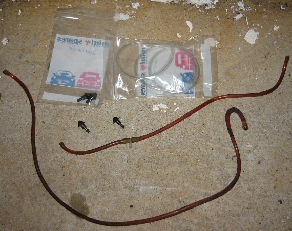
I figured I'd tackle the welding at the weekend, which was only a few days away. First I had to figure out what was wrong with the windscreen wiper jets and the handbrake cable so I could order some parts in time for the weekend. A quick inspection later and I ordered some new pipes and jet heads from Mini Spares, choosing express delivery so they'd arrive in time for the weekend.
Windscreen washers
The problem with the windscreen washers turned out to be a case of a crushed pipe (from being jammed behind the air filter casing), combined with one knackered jet head.
The design of the washer mechanism on my 1990 Mini is as follows: A plastic bottle that is positioned lower than the jet heads contains an electric motor which pumps water from the bottle into a plastic pipe. The pipe goes up the engine bay and terminates at a plastic T-piece which has two more pipes of the same diameter going to the right and left washer jet heads. These jet heads are D-type heads in that they have a D-shape that slots into D-shaped holes drilled into the scuttle panel, below the windscreen. The jet heads have an eyelet that the pressurised water is squirted out of. These eyelets can be aimed at various points on the windscreen by using a pin inserted into them and moving the pin around.
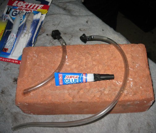
When I received the two new jet heads and pipe (with a 4mm internal hole diameter) from Mini Spares, I attached them to my Mini and ed them. I found that although they were effective, water also leaked out of the top of the pipes, which then dripped onto the fuse box. Not good.
Knowing that I could not get replacements in time for the re I worked out that the pipes would fit through the jet holes in the scuttle panel so I super-glued the top of the pipes to the jet heads to form a seal at the top of the pipes. Once dry, I fed the pipes through the scuttle panel and connected them to the T-piece. I ed the jet sprays, used a pin to aim the water at the middle of the windscreen on either side, and checked that there were no leaks.
For some reason on my car the T-piece is more over to the drivers side than the passenger's. While this may be by design or by the previous owner, it does cause an unequal water pressure at each jet. The shorter tube gets more pressure so more washer liquid is squirted onto the drivers side. By adding the same length of tube at either side of the T-piece the water pressure is equalised. However, this would require the T-piece to be situated behind the air filter case where it could easily become crushed again.
One nice note to make is that I contacted Mini Spares to complain about the pipe they sold me, and how it leaked when used with their jet heads. They apologised, saying that it is difficult to get the right diameter pipe these days, and that a technique they recommend is to submerge the pipe ends in hot water before placing over the ends of the washer jets, and that should form a water-tight seal. They also said they'd send me some more pipe and a couple of heads so I could 'have a play' and see for myself. Much better customer service than I've received from other parts dealers in the past.
The welding
It was now the weekend, so time to get down to some welding. I decided to tackle the two small holes next to the seatbelt mounting point first. They turned out to be nowhere near the seatbelt mounting but instead were on the outer sill under the side trim lip. One was in the middle of the section below the drivers door, and the other was at the front towards the front wheel.
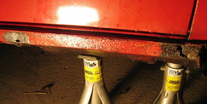
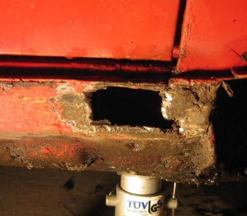
After removing the sill trim I blasted the area with a wire brush attachment on my drill to clean the area and to get an idea of how bad the holes were. The one in the middle wasn't too bad, but the one at the front got pretty big.
Next I cut away any rotten metal and rust and prepared the area (with an angle grinder!). I then cut some sheet steel to cover the holes and used a MIG welder to tack the pieces in place.
Once in place I used the MIG to seam weld the pieces to the sill. Well I say 'seam weld'. What I actually mean is I made a slow, steady, mess.
I'll admit I'm crap at welding, but no one else was available, so it was down to me. I found some pretty good 'how to' videos on YouTube showing me how to weld using a MIG welder. They were informative so if you don't know how to set up, use, and weld with a MIG welder, go search for "how to use a MIG welder" on YouTube.
Anyway, my beginners technique was to make lots of tiny welds along the edge of the new steel, angle grind them down, apply more weld to the gaps, then angle grind some more. It worked ok and the new metal ain't falling off I can tell you.
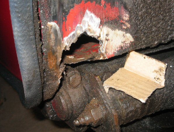
The tricky welding job was the hole described as near a subframe mounting. This was actually above the subframe in the rear left wheel arch on the lip that is actually a bottom corner of the left storage pocket to the left of the back-seat.
This hole was bigger than the MOT er had said, as discovered after blasting the area with the wire brush attachment. The hole would require an L-shaped piece of metal with a side-bit.
To come up with the replacement metal I used a piece of cardboard, cutting away bits and bending it until it covered the hole. I then used the cardboard as a template to cut out the same shape from some sheet steel. I then used two pliers to bend and shape the steel to fit the hole.
To prepare the area I used an angle grinder to lightly burn away all traces of under-seal and paint around the area so I can weld metal to metal.
Now there was only me here so what I did to start with was to place the metal piece over the hole where I wanted it, used one hand to hold it there by pushing on it with a pair of pliers, and then the other hand was holding the welder (both hands were covered by welding gloves). I positioned the welder nozzle where I wanted to tack the piece to the body and closed my eyes for 3 seconds and pulled the trigger. I closed my eyes because I had no third hand to hold the welding mask. Don't try this at home folks!
Safety warning: I had a bottle of water, a fire extinguisher, and a wet rag at hand in case there was a problem when I was welding. I'd also disconnected the car battery, and the alternator so that the welder did not damage either. If there was a fire I knew to turn the power to the welder off first before using the water/extinguisher/wet rag. I had also removed anything flammable on the inside of the car near where I was welding, such as carpet, foam, or trims.
With the metal piece held in place by one small weld I picked up the welding mask to protect my eyes and proceeded to add more tacks, followed by my messy weld-grind-weld-grind technique.
With all three welding jobs complete I smoothed the welds a bit more and applied some body filler to smooth any lumps and bumps and to ensure a watertight seal. I then left the car overnight.
The next day I smoothed down the body filler and applied several coats of primer to the sill followed by top paint to the sill, and black hammerite followed by underseal to the wheel arch weld.
Handbrake cable
Tightening the handbrake cable is fairly easy. Mine is the type with one cable at the front, so all I have to do is jack up both back wheels and place the car on axel-stands, unlock the locking nut on the handbrake cable by the lever inside the car, then tighten the other nut until the rear wheels cannot be moved with your hands with the handbrake lever pulled up three clicks. Then take off the handbrake and tighten up the locking nut against the other nut.
What proved difficult was solving the problem where the right rear wheel became locked on before the left.
After some reading I learned that with rear drum brakes there are adjusters at the top of the wheel hubs that wind in and out and push the shoes towards the drums taking up any slack.
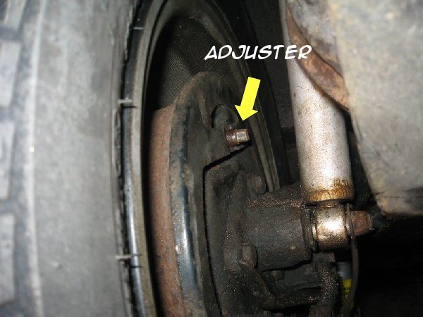
How it works: Look at the back of your rear wheel hub. See that square nut at the top? That is the back of a an adjuster. An adjuster is like the end of a ballpoint pen except it is shaped like a pyramid. As you screw it in, its pyramid head pushes out two metal bushes which in turn push out the top of the brake shoes towards the inner wheel hub. As your brake shoes wear down, winding this adjuster in closes the gap.
[Thanks to my Dad for filling in the blanks left by the Haynes manual.]
Now the problem with the adjusters on Minis is that the pyramid heads are square so you can only leave them in the 3, 6, 9 or 12 o'clock positions when you are done winding them in or out. Some do not realise this and you can damage them if you leave them set at any other angle, so remember this.
The problem I had was that my adjusters had not been moved in a long time and had seized. I tried lots of WD40 and even a blow torch but they wouldn't move! In the end I stripped down the wheel hubs and covered the adjuster in WD40 and left it overnight. The next day using a borrowed square spanner designed for the job I got the adjuster to move.
Putting the brake shoes back on is a pain in the ass I can tell you. Those two springs are so.. finicky!
With the wheel hub reassembled, I adjusted the nut a bit and ran the following :
With the handbrake off I lay under the back of the raised car and reached out with both hands to both wheels and spun them to feel how tight they were. I then raised the handbrake one click and repeated the wheel spinning . At two clicks the right wheel was harder to move but the left span easily. I adjusted the tensioner a bit more until both felt the same. At three clicks of the handbrake lever I could not move either wheel.
Happy with the handbrake, I got some assistance for a few minutes with the pressing of the brake pedal. When my assistant pressed the brake foot pedal I used my hands to see if I could turn each wheel. Both were equally locked which is good as making the adjustments that I did to the rear wheel hubs could potentially affect the rear braking, which is also a MOT failure.
I made sure that the adjuster was at a 3,6, 9 or 12 o'clock position when I left it and then lowered the car back to the ground and tightened the wheel nuts.
All finished, I carried out a few final inspections of my work before calling it a day.
I later took the Mini back to the MOT station for its re and I'm happy to say it passed.
Maybe I should think about switching MOT s to the summer next time.
Did you enjoy this article or find the information useful? Help keep Dave and his articles online by keeping him fed with coffee by clicking the link below. Cheers!

Next page - Having some Mini fun in the snow
Previous page - Door seal sill repair
Back to the Mini Project Main Menu

This website uses cookies. Click here to learn more about how and why we use cookies.